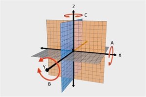
The goal of fixture design is to ensure the correct positioning of the workpiece on the fixture and to restrict its movement during the machining process. Manufacturers use a Cartesian coordinate system with three perpendicular axes: X, Y, and Z, to describe the position and movement of a workpiece.
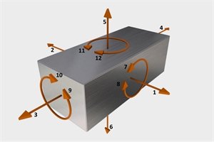
This coordinate system describes the potential linear movements along the X, Y, and Z axes, as well as rotational movements around the A, B, and C axes (corresponding to 12 possible directions of movement, including positive and negative directions). In vertical machining processes, the horizontal X-axis describes movement from side to side, denoted as 1 degree and 2 degrees. The horizontal Y-axis describes forward and backward movements, denoted as 3 degrees and 4 degrees. The vertical Z-axis represents upward and downward movements, denoted as 5 degrees and 6 degrees. The six rotational movements are clockwise and counterclockwise rotations around the three rotational axes: A-axis at 7 degrees and 8 degrees, B-axis at 9 degrees and 10 degrees, and C-axis at 11 degrees and 12 degrees.
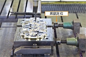
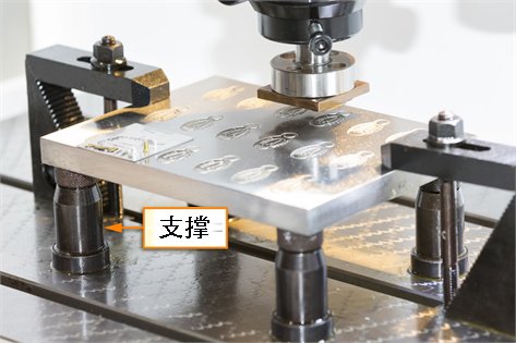
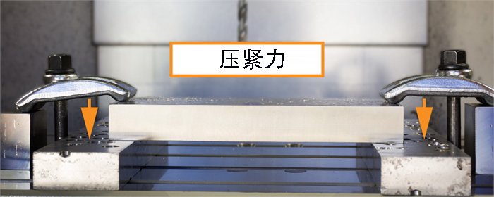
A proper workpiece fixture setup must limit all 12 directions of movement before machining begins. Support and positioning devices can restrict up to 11 degrees of freedom, while clamping will restrict the final degree of freedom in upward movement.